Quick Answer: Wi-Fi 7 mesh dead zones are almost always caused by node placement errors, not hardware defects. The fix involves strategic node spacing (no more than 30–40 feet between nodes), avoiding physical obstructions like concrete walls and appliances, elevating nodes off the floor, and enabling MLO (Multi-Link Operation) backhaul correctly. Most issues resolve with repositioning alone — before buying more hardware.
The promise of Wi-Fi 7 mesh was simple and, by the standards of consumer networking marketing, almost offensively bold: blanket coverage, zero dead zones, seamless roaming, multi-gigabit speeds everywhere in your home. The reality, predictably, is more complicated—often more frustrating than dealing with a PS5 Error CE-108255-1. Forums like Reddit's r/HomeNetworking are full of posts from users who spent $1,000 on a mesh kit only to find their smart TV buffering; if you are facing similar issues, check out 7 Quick Fixes for Smooth 4K Streaming to resolve your playback problems.
Some of that is hardware variation, which can be as puzzling as why your Google Home Max keeps disconnecting from Wi-Fi. Some of it is ISP throttling. But the overwhelming majority — and this is something most review sites bury in a footnote — is placement. Bad node placement. Counterintuitive node placement. Placement that looks right but violates how 802.11be actually behaves across real building materials.
This is not a simple "put your router in the middle of your house" guide, as optimizing a network requires more precision than learning how to fix Ecovacs Deebot T9 Error 4. Wi-Fi 7's Multi-Link Operation, 320 MHz channel support, and the way mesh backhaul actually negotiates connections in 2024–2025 hardware creates placement dynamics that are genuinely different from Wi-Fi 5 or 6 deployments. Getting this right requires understanding what's happening at the radio layer, not just following a diagram in the box.
Why Wi-Fi 7 Dead Zones Behave Differently Than Previous Generations
Wi-Fi 7 — formally 802.11be — adds meaningful complexity that changes the failure modes of mesh networks. The most important: MLO (Multi-Link Operation), which allows a single device to simultaneously communicate across 2.4 GHz, 5 GHz, and 6 GHz bands. In theory, this reduces latency and improves reliability. In practice, it introduces a new failure mode that's easy to miss.
When a node is placed poorly, MLO can actually mask the problem initially. A device near the edge of coverage will appear connected — it's getting signal on the 2.4 GHz link — but its 5 GHz and 6 GHz connections are marginal or dropped entirely. The throughput numbers look terrible, the latency spikes randomly, but the device never disconnects. Users often assume the hardware is broken, much like those who encounter a Ring Doorbell Pro offline after a Wi-Fi change and panic unnecessarily.
The 6 GHz band, which Wi-Fi 7 relies on heavily for its headline speeds, has a fundamental physical characteristic that vendors consistently understate: it barely penetrates walls. A single interior drywall partition can reduce 6 GHz signal strength by 6–10 dB. A concrete wall, brick exterior, or floor joists with foil vapor barrier can cause 20–30 dB attenuation — effectively killing 6 GHz connectivity between nodes or between node and client across that obstacle.
This is why a mesh system fails in dense houses, making it just as difficult to manage as a Roborock S7 Error 1 LiDAR turret obstruction.

The Real Topology of Your Home: What Mesh Systems Actually See
Before placing any node, you need a mental model of your home's RF environment. Not the floor plan — the signal environment. These are different things.
Mapping Physical Obstructions and Their RF Cost
Not all walls are equal. The materials in your home attenuate Wi-Fi signal at rates that vary dramatically by frequency — and 6 GHz behaves more like a short-range high-frequency signal than the 2.4 GHz you grew up with:
- Drywall (single layer): 2–4 dB loss at 5/6 GHz
- Drywall (double layer, fire-rated): 6–10 dB loss
- Brick or concrete block: 10–20 dB loss
- Reinforced concrete (poured): 20–30 dB or complete blockage
- Foil-backed insulation or radiant barriers: Near-complete signal block at 6 GHz
- Ceramic tile over cement board: 5–12 dB depending on thickness
- HVAC ducts (metal): Reflection and absorption, creates unpredictable shadow zones
A dead zone behind your refrigerator isn't the refrigerator blocking signal — it's the compressor motor, the metal body, and the metal-backed wall cavity behind it creating a combined 15–25 dB signal sink. Moving a node two feet to avoid that line of sight makes a measurable difference.
Old homes from the 1950s–1980s frequently have plaster-on-wire-mesh walls rather than drywall. That wire mesh acts as a partial Faraday cage and is notably worse for Wi-Fi signal than modern drywall construction. If you live in one of these homes and your mesh system is misbehaving, this is a significant factor that no vendor documentation mentions.
The Vertical Dimension: Floors and Ceilings
Multi-story homes introduce the dimension that flat-thinking placement advice ignores. Signal passing through a floor/ceiling assembly travels through:
- Hardwood or tile flooring
- Subfloor (plywood)
- Floor joists (wood or metal)
- Insulation (in newer construction, often foil-faced)
- Drywall ceiling
That's easily 12–18 dB of signal loss at 6 GHz — worse than going through two interior walls. Expecting a single node on your first floor to provide reliable 6 GHz backhaul to a node directly above it on the second floor is optimistic. It may work. It may not. Depending on your specific construction, it may work for six months and then degrade as you add 6 GHz clients that compete for that marginal link.
Node Placement Principles That Actually Hold Up in the Field
The 30-Foot Rule Is a Starting Point, Not a Rule
Most mesh vendor documentation recommends placing nodes 30–40 feet apart. This is derived from signal propagation models in "typical" construction — which is essentially an open office with drywall partitions. In homes with denser construction, the effective range for stable 6 GHz backhaul is closer to 15–25 feet through walls, or up to 30–35 feet in open plan with clear line of sight.
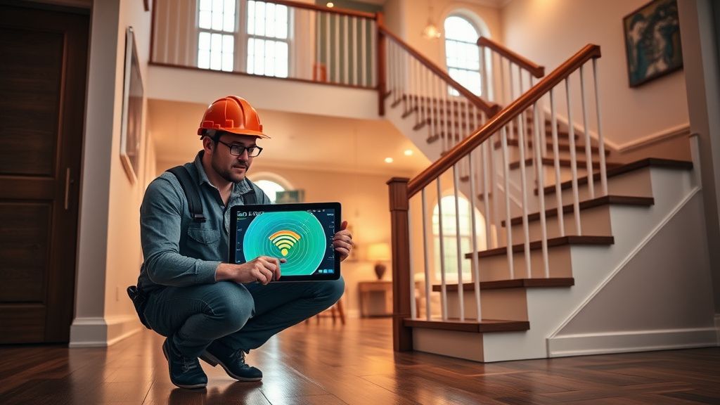
The correct method: walk the signal, don't measure the floor plan. Place a node tentatively, check the backhaul signal quality (most modern mesh systems expose this in the app as a signal strength percentage or link quality score), then move it until you find the balance point between coverage area and backhaul quality.
Critically, backhaul quality matters more than client coverage in mesh systems. A node with good client RSSI but poor backhaul will deliver frustratingly slow speeds because every packet to and from that node has to traverse a weak link back to the main router. Users on Reddit frequently describe this as "full bars, terrible speed" — which is exactly what a weak mesh backhaul looks like from the client side.
Height Matters More Than People Expect
Nodes placed on the floor lose substantial signal range because flooring materials absorb signal from below and the node is transmitting into obstacles rather than open space. The recommended height range for most residential environments is 3–5 feet off the floor — roughly countertop to shelf height.
Placing a node on top of a bookshelf at ceiling height sounds intuitively correct (higher = better coverage) but in practice often creates problems: ceiling-mounted nodes in multi-story homes push signal vertically into the floor above rather than horizontally across the current floor, and some mesh systems don't handle the resulting asymmetric signal pattern well in their roaming algorithms.
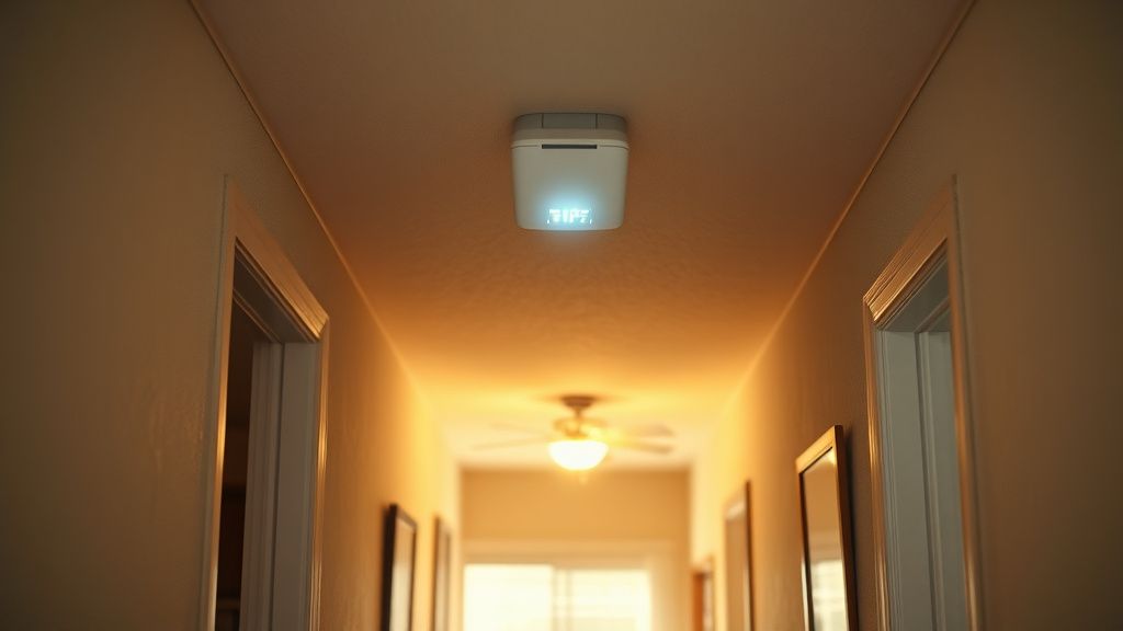
The sweet spot is mid-wall height, away from corners, and away from other transmitting devices (microwaves, cordless phones, baby monitors, and increasingly, other 6 GHz devices like the latest wireless VR headsets).
Avoiding the Corner Trap
Placing nodes in room corners is perhaps the single most common placement error. A node in a corner radiates signal into two walls and wasted space behind it, while only effectively covering a 90-degree arc toward the interior. That's roughly 25% of its possible coverage area utilized productively.
Nodes should be placed toward the center of the coverage area they're meant to serve — ideally in a hallway, near an open doorway, or on a shelf in a central room. This sounds obvious. In practice, it conflicts with where power outlets are, where furniture allows, and where the node won't be in anyone's way. The compromise between optimal placement and real-world constraints is exactly where dead zones are born.
MLO Backhaul Configuration: The Part Nobody Documents Properly
Wi-Fi 7 mesh systems use Multi-Link Operation for backhaul in ways that vary significantly between vendors — and most of them don't document which bands are actually being used for backhaul versus client access, or how to verify it.
TP-Link Deco BE85, Eero Max 7, ASUS ZenWiFi BQ16, and Netgear Orbi 970 all use different backhaul strategies. Some dedicate 6 GHz exclusively to backhaul. Some use MLO to aggregate backhaul across 5 GHz + 6 GHz simultaneously. Some fall back to 5 GHz backhaul automatically when 6 GHz link quality drops below a threshold — without telling you.
The practical implication: if your mesh system silently falls back to 5 GHz backhaul because your node placement doesn't support a strong 6 GHz link, you've paid for Wi-Fi 7 speeds and are getting Wi-Fi 6 backhaul performance. The client-facing speeds can drop by 40–60% depending on the traffic load, and you'll only notice it under sustained throughput testing, not casual browsing.
The dirty secret of Wi-Fi 7 mesh: Most consumer mesh apps don't expose the actual backhaul link speed or band in real-time. They show you a reassuring checkmark or signal strength bar. The only way to verify what's actually happening is through the web UI (if your system has one) or third-party tools like WiFi Analyzer on Android, which can show you the negotiated rates on nearby networks.
This creates a trust problem. Users who placed nodes suboptimally may be operating a degraded Wi-Fi 7 system for months without knowing it. The vendor app says everything is fine. The actual throughput to far nodes tells a different story.
Real Field Reports: What Actually Happens at Scale
The Open-Plan Apartment That "Just Works"
Across multiple user reports in Eero and TP-Link Deco communities, open-plan apartments — studio to two-bedroom, under 1,200 square feet, concrete construction but open interior — consistently deliver the promise. Two-node setups achieve strong 6 GHz backhaul, MLO functions as intended, and real-world speeds measured at client devices are genuinely improved versus Wi-Fi 6E setups.
This is the scenario vendors are demonstrating at trade shows. It's real. It's just not the majority use case.
The 1970s Ranch House: A Recurring Nightmare
A thread on r/HomeNetworking from early 2024 detailed a user's experience with a three-node Eero Max 7 system in a 2,200 sq ft ranch home with original construction: plaster walls, aluminum wiring, and a centrally located HVAC unit with large metal ductwork. The system performed excellently in the kitchen/living area but delivered unusable speeds (under 20 Mbps even with 500 Mbps ISP service) in the master bedroom and back office.
The resolution required four specific changes: moving one node from the master bedroom corner to the hallway, repositioning the main router from the TV console (floor level) to a wall shelf at 48 inches height, disabling the 6 GHz backhaul preference on the node that traversed the HVAC utility room (forcing 5 GHz backhaul for that hop), and adding a fourth node rather than running the system as a three-node network across that floor plan.
None of these steps were in the Eero documentation. They were derived from trial and error, WiFi Analyzer readings, and advice from the broader community.
Smart TVs as the Canary in the Mine
Smart TVs are revealing diagnostic tools for mesh dead zones, which is part of why so many Wi-Fi 7 mesh complaints originate from TV placement issues. TVs are stationary, they're frequently placed against exterior walls (terrible for signal), they're often behind large metal OLED/QLED panels that can themselves attenuate signal, and the Wi-Fi chipsets in most smart TVs — even premium 2024 models — are not Wi-Fi 7 capable.
This matters because a smart TV connecting on Wi-Fi 5 or 6 in a Wi-Fi 7 mesh network will still use the band steering and roaming algorithms of the mesh system, but it won't benefit from MLO. It's entirely dependent on a single-band connection. If that band has marginal coverage, the TV buffers. This is frequently blamed on the streaming service or the ISP, when it's actually a mesh placement problem combined with a legacy Wi-Fi client that can't take advantage of the new system's resilience features.
The fix for smart TV dead zones specifically: place a node within 15–20 feet of the TV with clear or near-clear line of sight. Don't route the connection through walls if avoidable. This is one case where a dedicated node close to the TV — even if it seems redundant with broader coverage — consistently resolves streaming issues that "should" work based on overall coverage maps.
Counter-Criticism: Is Mesh Really the Answer Here?
Not everyone agrees that mesh is the right architecture for dead zone elimination, and the debate is worth engaging honestly rather than burying.
Wired Ethernet backhaul — running physical CAT6 or CAT6A cable to access points — eliminates the backhaul signal quality problem entirely. A wired access point in the back bedroom has exactly the same throughput as the main router, regardless of walls, HVAC, or construction materials. For users willing to run cable, this is objectively the more reliable architecture, and it works with Wi-Fi 6E or even Wi-Fi 6 hardware at a lower cost than Wi-Fi 7 mesh.
The mesh marketing pitch implicitly dismisses this option because "nobody wants to run cables." That's sometimes true and sometimes a convenient excuse to sell more expensive wireless hardware. Rental units, retrofitted homes without accessible wall cavities, and multi-tenant buildings are genuine cases where cabling is impractical. But many homeowners who buy mesh systems could cable their homes if they understood the performance tradeoffs — they just weren't offered that option by the retailer or the review they read.
Powerline adapters are the middle ground, and their reputation is mixed for good reason. In homes with older electrical wiring, interference, or multiple circuit breakers, powerline performance is unpredictable. In homes with clean, modern electrical installations, they work reasonably well as wired backhaul substitutes. They're not glamorous, they don't make for a good unboxing video, and vendors have no incentive to recommend them.
There's also the valid criticism that Wi-Fi 7 mesh systems at the $600–$1,200 price tier are frequently sold to users with 100–300 Mbps ISP connections that don't need the capability being sold. The dead zone problem for those users would be solved equally well by a $200 Wi-Fi 6 mesh kit with better placement — and the placement advice in this article would apply identically.
The Practical Placement Protocol: A Step-by-Step Field Process
Step 1: Audit Before You Place
Walk every room in your home with your phone running a signal strength app (WiFi Analyzer on Android, Network Analyzer on iOS). Map where the signal from your existing router or nodes drops below –70 dBm — that's the threshold below which 5 GHz and 6 GHz connections become unreliable. Note the physical obstructions between those weak zones and your nearest existing node.