Quick Answer: Mesh Wi-Fi 7 dead zones persist even in modern multi-node systems due to misplaced nodes, interference on the 6 GHz backhaul, firmware bugs, and poor channel planning. Fix them by auditing node placement, optimizing backhaul topology, tuning MLO channel assignments, and validating with real signal mapping — not just the vendor app's cheerful coverage bubbles.
There's a particular kind of frustration that sets in around week three of owning a mesh Wi-Fi 7 system. The marketing promised seamless roaming, wall-penetrating coverage, and enough bandwidth to stream 8K video to every corner of your home simultaneously. Then you walk into the kitchen or the far bedroom or that weird hallway near the water heater, and your phone shows one bar of Wi-Fi, or worse, clings stubbornly to a node three rooms away with a signal so degraded it's functionally useless.
This is not a new problem. It has existed through every generation of mesh networking — 802.11ac, Wi-Fi 6, Wi-Fi 6E — and Wi-Fi 7, despite its genuine engineering advances, has inherited most of the same failure modes while introducing a few new ones of its own.
The difference now is that the systems are more expensive, the marketing claims are more ambitious, and the gap between promise and reality feels correspondingly wider.
Why Wi-Fi 7 Mesh Dead Zones Still Happen in 2024
Wi-Fi 7 (802.11be) brings Multi-Link Operation (MLO), 320 MHz channel widths on the 6 GHz band, 4K-QAM modulation, and theoretical throughput numbers that would have seemed science fiction five years ago. None of this automatically solves dead zone problems, because dead zones are rarely caused by insufficient bandwidth. They're caused by geometry, physics, and software decisions that no standard alone can fix.
The Geometry Problem
Mesh systems rely on node placement. Every vendor ships their product with coverage maps that assume open-plan homes with drywall partitions. Real homes have poured concrete, stone fireplaces, mirror-backed closets, stairwells acting as RF chimneys, and HVAC returns punched through walls at exactly the wrong angle. The physics of radio propagation doesn't care about your router's spec sheet.
The 6 GHz band — Wi-Fi 7's primary differentiator — has significantly higher path loss than 2.4 GHz. What this means in practice: a Wi-Fi 7 node that claims to cover 3,000 square feet will cover 3,000 square feet of open air. Add two standard interior walls between client and node, and that 6 GHz connection degrades sharply. The same system's 2.4 GHz radio will still reach, but it can't carry the backhaul traffic efficiently, which creates a cascade effect across the whole mesh.
The MLO Complexity Tax
Multi-Link Operation is Wi-Fi 7's signature feature. It lets devices simultaneously transmit and receive across multiple radio bands, reducing latency and improving aggregate throughput. In theory. In practice, the interaction between MLO link selection, roaming decisions, and backhaul topology creates edge cases that vendors are still patching out as of mid-2024.
A common complaint on forums like SmallNetBuilder and r/HomeNetworking: a client device that supports MLO will sometimes negotiate a link combination that isn't actually the best path — particularly when one node is at the edge of its 6 GHz coverage range. The device "thinks" it has a good connection because the aggregate MLO throughput metric looks acceptable, while in practice the 6 GHz link is dropping packets at a rate that wrecks TCP retransmission behavior. The client doesn't roam because the system reports it as connected. The user experiences this as mysteriously slow Wi-Fi in one room, similar to why your Wi-Fi 7 network still drops packets due to MLO stacking issues.
This isn't hypothetical. Threads on the TP-Link Deco community forum and ASUS ZenWiFi subreddits document exactly this behavior, much like the technical insights found in this guide on why your Wi-Fi 7 is dropping packets, and several firmware updates in 2024 have explicitly listed "improved MLO link evaluation" in their changelogs — which is vendor-speak for "we were making bad decisions and we fixed some of them."
The Backhaul Illusion
Most consumer mesh systems use a dedicated 6 GHz radio for node-to-node backhaul. This is marketed as a major advantage over tri-band systems that sacrifice a 5 GHz channel for backhaul. The advantage is real — but the implementation has sharp edges.
The 6 GHz backhaul works well when nodes have clear line-of-sight or minimal obstruction. The moment you place a satellite node in a room separated from the primary node by a concrete slab or a kitchen full of metal appliances, the 6 GHz backhaul degrades. Most systems will not automatically fall back to 5 GHz backhaul gracefully. They'll cling to the 6 GHz link, retrying, degrading performance for every client connected to that satellite. Some systems do this more gracefully than others; Eero's backhaul management has historically been more conservative about 6 GHz in weak signal conditions, while some competitors have been more aggressive (and consequently more prone to this failure mode).

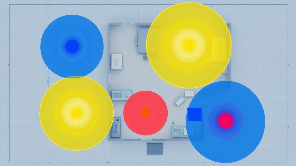
Step 1: Stop Trusting the Vendor App Coverage Map
Almost every mesh system ships with a companion app that displays a cheerful coverage map — usually concentric colored circles emanating from each node. These maps are generated algorithmically based on expected signal propagation models. They do not reflect your actual home.
The first operational step in fixing dead zones is to stop looking at that map and start measuring.
Tools That Actually Tell You What's Happening
Wi-Fi Analyzer apps (Android: WiFiAnalyzer, iOS: Network Analyzer Pro, or commercial tools like Ekahau Sidekick for serious deployments) let you walk through your home and record actual RSSI values and noise floor readings at each location. What you're looking for:
- RSSI below -70 dBm at any location where you expect usable coverage is a problem
- Noise floor above -85 dBm on any channel you're using indicates interference competition
- The gap between RSSI and noise floor (SNR) falling below 20 dB is where you'll see real-world throughput collapse
The vendor app showing "good coverage" and your measurement showing -75 dBm RSSI with -82 dBm noise floor are not contradictions. The vendor app is wrong, or at least it's telling you something different from what you think it's telling you.
Walking the Signal Map
Walk your home slowly, measuring RSSI at the height where devices are typically used — table height for laptops, roughly 1 meter for smartphones. Document where the signal drops. Note what's between you and the nearest node. This is tedious and feels unnecessary, but it's the only way to understand where your actual problems are.
Pay particular attention to:
- Rooms on the far side of appliance-heavy kitchens
- Spaces on different floors from any node
- Areas near large metal structures (water heaters, HVAC units, metal shelving)
- The outdoor coverage edge if you care about patio/deck connectivity
Step 2: Node Placement Audit — The Real Rules
The single highest-impact change in most dead zone situations is moving a node. Not adding a node — moving an existing one.
The 60% Rule for Node-to-Node Distance
Nodes should be placed roughly at the point where the parent node's signal reads -60 to -65 dBm. Not closer, not at the edge of coverage. The reason: you want each satellite node to have a healthy backhaul connection to its parent, which means placing it where the parent's signal is still strong — while simultaneously extending coverage into a new area.
Most users place satellite nodes too far from the primary because they're trying to cover maximum distance with minimum hardware. The result is a satellite node with a weak backhaul connection that underperforms for every client behind it.
The better mental model: nodes are repeaters with overhead costs. Every hop through a satellite adds latency and reduces available bandwidth. You want each hop to be clean and short rather than long and marginal.
Line of Sight vs. Wall Penetration Planning
On the 6 GHz band, every wall costs you. Rough real-world attenuation estimates (these are well-established figures from RF engineering literature, not proprietary test data):
| Material | Approximate attenuation at 6 GHz |
|---|---|
| Standard drywall | 3-5 dB |
| Wood frame with insulation | 5-8 dB |
| Brick | 10-15 dB |
| Concrete (poured) | 15-25 dB |
| Metal/Foil-backed insulation | 20+ dB, often complete block |
Stacking two concrete walls between parent and satellite node means you may have eaten 30-50 dB of your link budget before you've accounted for any other loss. At 6 GHz, that's often the entire usable range.
Multi-Floor Deployments
Floors are the hardest problem in home mesh networking. The signal path between a node on the ground floor and a client on the second floor must travel through flooring material — often concrete subfloor, engineered wood, or a combination — plus any furniture and cabling infrastructure in between.
The practical fix is vertical placement: position nodes near staircases or floor openings where signal can travel through air rather than solid material. A satellite node placed at the top of a staircase often outperforms one placed in the center of the second floor, because the staircase creates a low-attenuation air path for the backhaul signal.
Step 3: Channel and Bandwidth Configuration — Don't Let Autopilot Drive
Wi-Fi 7 systems default to automatic channel selection. This is convenient and wrong surprisingly often.
The Auto-Channel Problem
Automatic channel selection runs during router startup, not continuously. The channel your system selected at 3am last Tuesday might be contested by a neighbor's new router they set up last weekend. The system won't notice unless you reboot.
More specifically for Wi-Fi 7: the 6 GHz band has significantly less interference than 2.4 or 5 GHz because the band requires Wi-Fi 6E or newer devices to access it. However, the available channels aren't evenly useful. In the US, the 6 GHz band offers channels 1-233, but usable non-overlapping channels at 320 MHz width are limited, and regulatory restrictions (AFC requirements for standard power, indoor-only for low-power) affect which channels are legal to use at what power levels.
Manual Channel Assignment Strategy
For a two-node system:
- Use a Wi-Fi analyzer to identify the least-congested 6 GHz channel in your environment
- Assign the backhaul to that channel manually if your system supports it (many do not expose this control — a significant firmware limitation)
- For the 5 GHz client radio, channels 36-48 are typically less congested than 149-165 in dense residential areas, though this varies by location
- Leave 2.4 GHz on auto or lock it to channel 1, 6, or 11 (non-overlapping) based on your neighbor scan
The honest limitation: most consumer mesh systems do not expose granular channel control for backhaul. You're dependent on firmware decisions. Systems that do expose this (certain ASUS ZenWiFi models, some Netgear Orbi configurations, open-source platforms like OpenWrt on compatible hardware) give you substantially more control — and correspondingly more ability to misconfigure things badly.

Step 4: Firmware — The Invisible Variable That Breaks Everything
This section exists because of how frequently it gets overlooked.
The Real Cost of Running Stale Firmware
Mesh Wi-Fi systems are, at their core, complex embedded Linux systems running sophisticated RF management software, backhaul negotiation protocols, and client steering algorithms. They have bugs. Sometimes serious ones.
A documented example: in early 2024, multiple users on the r/eero subreddit reported that after a specific firmware update, satellite nodes would intermittently drop their backhaul connection and not automatically reconnect without a manual reboot. The thread grew to several hundred replies, with users developing workarounds including power cycling schedules and — this is the operational reality of mesh networking — running a Raspberry Pi script to ping a satellite node and trigger an outlet timer if the node became unreachable.
That's a $500+ mesh networking system requiring a homemade watchdog script to stay operational. It's not unusual. Almost every major mesh vendor has shipped firmware that introduced connectivity regressions, and the typical resolution timeline is 2-6 weeks after acknowledgment.
Firmware Update Strategy
- Don't auto-update immediately: If your system allows deferring updates, watch community forums for two weeks after a major firmware release. Let other users find the regressions.
- Note your current version before updating: If something breaks post-update, you need to know what you updated from.
- Check for release notes: Most vendors post firmware changelogs, though they're often incomplete. Terms like "improved stability," "enhanced roaming performance," and "backhaul optimization" are flags that something was broken and may or may not be fully fixed.
- Factory reset after major firmware jumps: Counterintuitive but often necessary. Large firmware version changes sometimes carry over corrupted configuration state that causes subtle performance problems. The fix — which no vendor documentation ever tells you — is a factory reset and clean reconfiguration.
Step 5: Client Roaming Behavior — The Part the Router Can't Fully Control
Dead zones aren't always about signal. Sometimes they're about a client device that refuses to roam to a better node.
Sticky Client Syndrome
802.11r (fast BSS transition) and 802.11v/k (BSS transition management) are supposed to enable smooth roaming across mesh nodes. Wi-Fi 7 improves on this with enhanced MLO coordination. In practice, client roaming behavior is still substantially controlled by the client device's driver, not the access point.
An iPhone in your kitchen that connected to the bedroom node when you were on a call might cling to that node even as you move to the opposite corner of the house. The iPhone driver decides when to roam, not your mesh system. The mesh system can send BSS transition requests suggesting the client move, but the client can and does ignore them.
The result: a device that appears to have "dead zone" connectivity problems that are actually sticky-client problems. The fix is different in each case.
How to distinguish them:
- Forget and reconnect the Wi-Fi network while standing in the problem area. If throughput immediately improves, you had a sticky client issue, not a coverage problem.
- Check which node the client is associated with (the vendor app usually shows this). If it's associated with a far node despite a closer one being available, that's roaming behavior, not coverage.
Minimum RSSI Threshold Configuration
Some enterprise-grade and prosumer mesh systems allow you to configure a minimum RSSI threshold below which a client will be disassociated from a node, forcing it to roam. This is sometimes called "band steering" or "client steering aggressiveness" in vendor UIs. Setting this too aggressively causes clients to ping-pong between nodes. Setting it too conservatively means sticky clients never roam.
The sweet spot is typically -75 to -80 dBm as a disassociation threshold, but it depends on your node density and the walking patterns in your home. A home where people mostly sit in fixed locations needs different tuning than one where someone carries a device through every room all day.
Step 6: Wired Backhaul — The Fix Nobody Wants to Do But Everyone Should
If you have the ability to run ethernet between nodes — even one or two of them — do it.
Why Wired Backhaul Changes the Calculus Entirely
Wireless backhaul, regardless of how good the 6 GHz link is, adds overhead, introduces latency, and creates a shared medium contention problem. A satellite node serving 10 clients is also sharing bandwidth with the parent node's backhaul traffic on the same radio. Wired backhaul offloads that contention entirely.
More importantly: wired backhaul eliminates the placement constraints around backhaul signal strength. You can put a satellite node exactly where client coverage is needed, not where backhaul signal quality permits.
Practical Wired Backhaul Options
Most people assume running ethernet means tearing open walls. Often it doesn't:
- **Existing coax with MoCA adap
Bu makale affiliate linkleri içermektedir.